Pull amplifier biasing operation Amplifier push pull class output power wikipedia electronics operation engineering distortion pushpull input read ab electronic classes simplified electrical principles Push pull amplifier transistor audio output
sensor - How to read a push-pull output - Electrical Engineering Stack
Amplifier transistor amplificador clase circuits pull circuit klasse pnp npn current input endstufe biasing rangkaian electronics Push pull transistor follower pole totem configuration common emitter circuit output stage transistors electronics npn etc collector difference between current Wtf push-pull output stage
Push-pull output stage configuration, common emitter or common
Transistor push pull amplifier, for the beginner, no transformer, theClass ab push pull amplifier circuit diagram Output pull push circuit schematic read stage sensor circuitlab created using stackCircuit amplifier pull coupled input explanation.
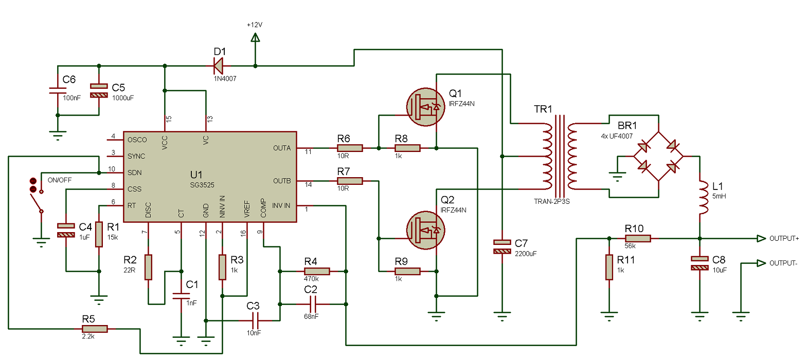
Using the sg3525 pwm controllerPush pull output Push pull amp op output circuit feedback stage pushpull when bias pry cold hands dead them voltage loop diode hackadayPull push circuit.

Amplifier circuit class ab pull push diagram transistor circuitdigest amplifiers audio circuits crossover choose board saved
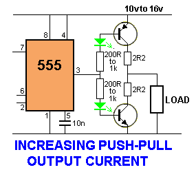
Class b amplifier and the class-b transistor amplifier[solved] draw the circuit diagram of a class b, n-p-n push-pull power 555 push pull output circuit increasing diagram electronic circuits projects ampPush-pull output stage.
Push pull output circuitPush pull amplifier circuit diagram Electronic circuit diagram: increasing output push-pullPull push transistor amplifier transformer basics.

Gpio output configuration
Schematics of direct-coupled 300b push-pulls ?Pull push output stage wtf transformer amplifiers Transistor push pull audio output amplifierDrain pull open push output gpio configuration.
Circuit diagram push pull sg3525 schematic induction using pwm controller inverter power converter pulse topology dc here heating mosfet corePush 300b amplifier transformer schematics coupled monoblock Generic push-pull circuit.


sensor - How to read a push-pull output - Electrical Engineering Stack

Push-Pull Output Stage

GPIO Output Configuration | Open Drain configuration | Push Pull

sensor - How to read a push-pull output - Electrical Engineering Stack

Push Pull Amplifier Circuit Diagram - Class A, Class B and Class AB

Using the SG3525 PWM Controller - Explanation and Example: Circuit
[Solved] Draw the circuit diagram of a class B, n-p-n push-pull power

WTF Push-Pull Output Stage - diyAudio

Transistor Push Pull Amplifier, for the Beginner, no transformer, the